

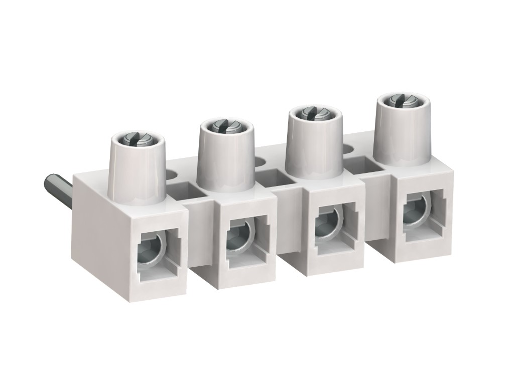
322-SVW (-DS)
Steckverbinderklemmleiste
Schraubanschluss & Steckerstift, für vertikale Steckrichtung, langer Steckerstift
BESCHREIBUNG
The plug-in terminal strip 322-SVW is available in 10 mm pitch with 2 to 12 poles. It has one screw connection per pole and one vertical pin for the connection to the socket of the female counterpart. In combination with the 322-FBG plug-in terminal strip, this connector is particularly well suited for PCBs. The plug-in direction to the PCB is horizontal. When used in combination with a type 323-FBW plug-in terminal strip, the contact pressure is applied by a stainless-steel spring thus providing excellent electrical contact. Due to the guided plug insertion from top, this angular plug-in connector combination is well suited for challenging mounting conditions. The through-wiring for this angular plug-in connector with plug-in terminal strip 323-PHFBW is achieved by means of screw connections. The individual consumer is wired at the plug connection. The wire protector of the “DS”-version reliably prevents damage to multi-wire flexible conductors by the turning screw. These terminals strips can be screw-mounted on a substrate.
ALLGEMEINE DATEN
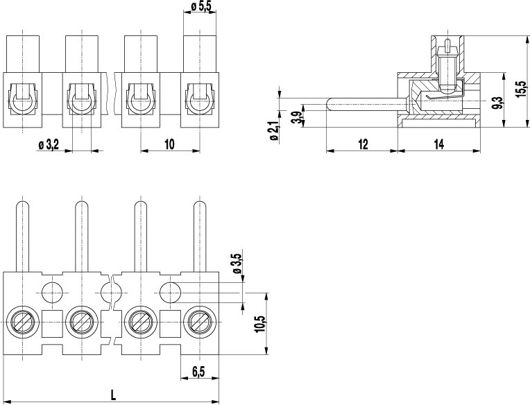
Raster: 10.00 mm
Polzahlen: 2 - 12
Verwendbar mit: 322-FBG(-DS), 323-FBW(-DS), 323-PHFBW(-DS)
Anwendung: Applications that require to easily open and close not energised circuits.
TECHNISCHE DATEN
Spannbereich:
ohne Drahtschutz
mit Drahtschutz:
Nennquerschnitt: 2.5 mm²
Abisolierlänge: 7 mm ± 0.5 mm
Überspannungskategorie
III
III
II
Verschmutzungsgrad
3
2
2
Bemessungsspannung
III
III
II
Bemessungsstoßspannung
6 kV (2.5kV)
6 kV (2.5 kV)
6 kV (2.5 kV)
Bemessungsstrom: 15 A
Bemessungsisolationsspannung: 450 V nach EN 60998-1
Drehmoment: 0.5 Nm
Andere Spezifikationen: Bemessungsdaten gelten in Verbindung mit 323-FBW(-DS) und isolierender Unterlage. Werte in Klammern gelten bei Verwendung ohne isolierende Unterlage.
ZULASSUNGEN
|
Strom [A] |
Spannung [V] |
Gruppe |
AWG |
Drehmoment [Nm] |
|
|---|---|---|---|---|---|

|
20 | 300 | B | 18 - 12 | 0.51 |

|
15 | 300 | B | 26-10 [1] | 0.51 |
| 10 | 300 | D,E | 26-10 [1] | 0.51 |
TECHNISCHE ZEICHNUNGEN
MATERIALDATEN
Gehäusematerial: PA, natural, V-2
Kriechstromfestigkeit: CTI ≥ 600
Isolierstoffgruppe: I
Temperaturgrenzen: -40°C up to 100°C
Schraube: M3; zinc plated steel, blue passivated
Drahtschutz: Tin plated tin bronze
SONDERAUSFÜHRUNG / ZUBEHÖR
- Beschriftungsmöglichkeiten auf den Schraubenführungen
- Vorauseilender Stecker für Schutzleiterkontakt
- Gehäuse aus Spezial-Polyamid z.B. für Hausgeräte


