

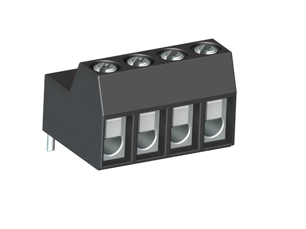
970-LH (-DS)
PCB Connector
Screw connection, right angle solder pin, pottable
BESCHREIBUNG
The 970-LH series PCB screw connector with a pitch of 5 mm features an angled solder pin is particularly suited for potting printed circuits. For such potting applications, the solder pin is sealed at the housing opening against seeping casting resin. This PCB screw connector is available in 2- to 12-pole design and can be mounted side-by-side without pole loss. Wire protection in DS-design reliably prevents damage to stranded wires by the screw. The wire entrance is parallel to the PCB whereas the casting resin surface is vertical to the wire entrance. Version 971-LH alternatively provides wire entrance vertical to the PCB.
ALLGEMEINE DATEN
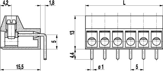
Raster: 5.00 mm
Polzahlen: 2 - 12
TECHNISCHE DATEN
Spannbereich:
ohne Drahtschutz
mit Drahtschutz:
Nennquerschnitt: 2.5 mm²
Abisolierlänge: 8 mm ± 0.5 mm
Überspannungskategorie
III
III
II
Verschmutzungsgrad
3
2
2
Bemessungsspannung
250 V
320 V
630 V
Bemessungsstoßspannung
4 kV
4 kV
4 kV
Bemessungsstrom: 24 A
Bemessungsisolationsspannung: 250 V acc. to EN 60998-1
Bohrung in der Leiterplatte: ø 1.3 mm
Drehmoment: 0.5 Nm
ZULASSUNGEN
|
Strom [A] |
Spannung [V] |
Gruppe |
AWG |
Drehmoment [Nm] |
|
|---|---|---|---|---|---|

|
20 | 300 | B | 22-12 [1] | 0.51 |
| 10 | 300 | D | 22-12 [1] | 0.51 | |

|
20 | 300 | B | 26 - 12 | 0.51 |
| 10 | 300 | D, E | 26 - 12 | 0.51 |
| Aktuell [A] |
Spannung [V] |
Querschnitt [mm2] |
AWG |
DREHMOMENT |
|
|---|---|---|---|---|---|

|
24 | 400 | 2.5 |
TECHNISCHE ZEICHNUNGEN
MATERIALDATEN
Gehäusematerial: PA, grey, V-0
Kriechstromfestigkeit: CTI ≥ 600
Isolierstoffgruppe: I
Temperaturgrenzen: -40°C up to 100°C
Klemmkörper: Tin plated brass
Schraube: M3; zinc plated steel, blue passivated
Lötstift: ø 1 mm; tin plated copper
Drahtschutz: Tin plated tin bronze
SONDERAUSFÜHRUNG / ZUBEHÖR
- CN: Consecutive Numbering
- SM: Special Marking (please provide sketch)
- G05: Gold Plating (5 micro inches)
- G30: Gold Plating (30 micro inches)
- S30: Silver Plating (30 micro inches)
- WG: Wire Guide
- Self-Adhesive marking strip BST-5.00
- Different pin lengths
- 970-J1, Jumper


