

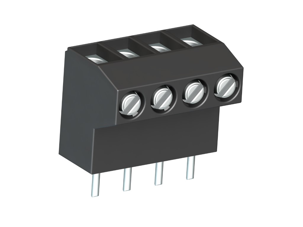
971-LH (-DS)
PCB Connector
Screw connection, vertical wire entry, pottable
BESCHREIBUNG
The 971-LH series PCB screw connector with a pitch of 5 mm is particularly suited for potting printed circuits. For such potting applications, the solder pin is sealed at the housing opening against seeping casting resin. This PCB screw connector is available in 2- to 12-pole design and can be mounted side-by-side without pole loss. Wire protection in DS-design reliably prevents damage to stranded wires by the screw. The wire entrance is located vertical to the PCB - the casting resin surface is also vertical to the wire entrance. Version 970-LH alternatively provides wire entrance parallel to the PCB.
ALLGEMEINE DATEN
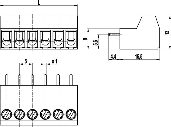
Raster: 5.00 mm
Polzahlen: 2 - 12
TECHNISCHE DATEN
Spannbereich:
ohne Drahtschutz
mit Drahtschutz:
Nennquerschnitt: 2.5 mm²
Abisolierlänge: 8 mm ± 0.5 mm
Überspannungskategorie
III
III
II
Verschmutzungsgrad
3
2
2
Bemessungsspannung
250 V
320 V
630 V
Bemessungsstoßspannung
4 kV
4 kV
4 kV
Bemessungsstrom: 24 A
Bohrung in der Leiterplatte: ø 1.3 mm
Drehmoment: 0.5 Nm
ZULASSUNGEN
|
Strom [A] |
Spannung [V] |
Gruppe |
AWG |
Drehmoment [Nm] |
|
|---|---|---|---|---|---|

|
20 | 300 | B | 22-12 [1] | 0.51 |
| 10 | 300 | D | 22-12 [1] | 0.51 | |

|
20 | 300 | B | 26 - 12 | 0.51 |
| 10 | 300 | D, E | 26 - 12 | 0.51 |
| Aktuell [A] |
Spannung [V] |
Querschnitt [mm2] |
AWG |
DREHMOMENT |
|
|---|---|---|---|---|---|

|
24 | 400 | 2.5 |
TECHNISCHE ZEICHNUNGEN
MATERIALDATEN
Gehäusematerial: PA, grey, V-0
Kriechstromfestigkeit: CTI ≥ 600
Isolierstoffgruppe: I
Temperaturgrenzen: -40°C up to 100°C
Klemmkörper: Tin plated brass
Schraube: M3; zinc plated steel, blue passivated
Lötstift: ø 1 mm; tin plated copper
Drahtschutz: Tin plated tin bronze
SONDERAUSFÜHRUNG / ZUBEHÖR
- Consecutive numbering
- Special marking according to drawing
- Self-adhesive marking strip BST-5,00
- Pitch of 10 mm for larger clearance and creepage distances
- Further solder pin lengths on request
- Version with extended wire entrance
- Version with larger clamping range
- Double wire protector as bridge


