

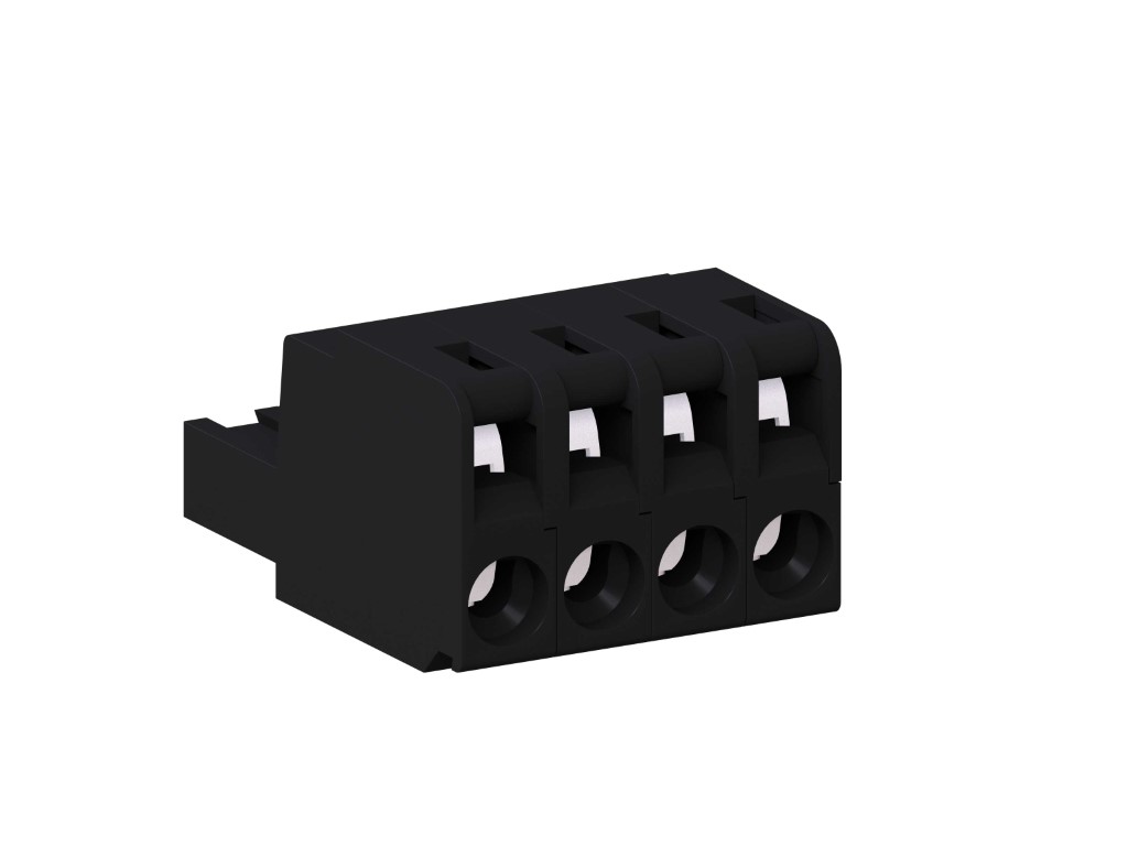
121-F-111
Plug Connector
Spring clamp connection
GENERAL INFORMATION
TECHNICAL DATA
Clamping Range:
solid / flexible / AWG
0.2 - 4 mm² / 0.2 - 2.5 mm² / 24 - 12 AWG
0.2 - 4 mm² / 0.2 - 2.5 mm² / 24 - 12 AWG
Rated cross section: 2.5 mm²
Wire stripping length: 8.5 mm ± 0.5 mm
Over Voltage Category
II
Pollution Severity Level
2
Rated Voltage
320 V
Rated Impulse Voltage
2.5 kV
Rated current: 12 A
Rated insulation voltage: 130 V acc. to EN 60998-1
Download PDF
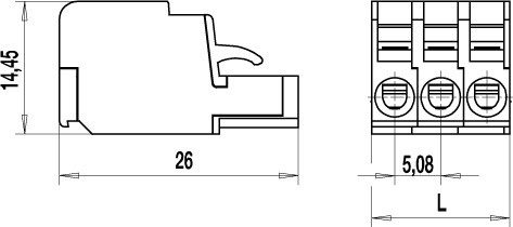
TECHNICAL DRAWINGS
MATERIALS
Moulding: PA, grey, V-0
Comparative tracking index: CTI ≥ 600
Insulating group: I
Temperature range: -40°C up to 100°C
Spring: Copper alloy, tin plated
Pressure clamp: Copper alloy, tin plated
Contact spring: Stainless strip steel
OPTIONS / ACCESSORIES
- Consecutive numbering
- Special marking according to drawing
- Self-adhesive marking strip BST-5,08
- Coding elements 120-K
- Connectors equipped with coding elements on request
- Strain relief
- Terminal pliers 120-F


