

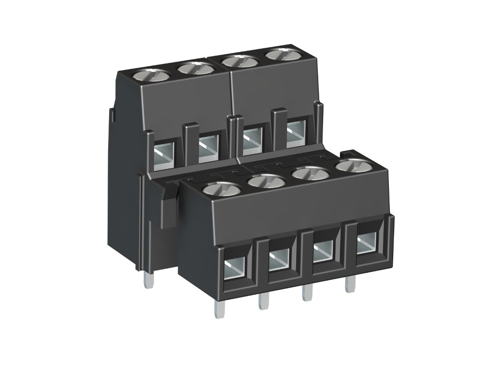
140-B-151 /-153
PCB connector
Screw connection, interlocking (only -153), two-tier version
GENERAL INFORMATION
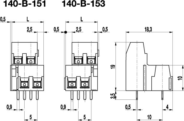
Pitch: 5.00 mm
No. of poles: 4 + 6
Additional information: Ordering information: -151: Front PCB connector is offset to the right -153: Front PCB connector is offset to the left
TECHNICAL DATA
Clamping Range:
0.14 - 1.5 mm² / 0.14 - 1.5 mm² / 26 - 16 AWG
Rated cross section: 1.5 mm²
Wire stripping length: 6 mm ± 0.5 mm
Over Voltage Category
III
III
II
Pollution Severity Level
3
2
2
Rated Voltage
160 V
160 V
320 V
Rated Impulse Voltage
2.5 kV
2.5 kV
2.5 kV
Rated current: 14 A
Rated insulation voltage: 250 V acc. to EN 60998-1
Hole in PCB: ø 1.2 mm
Torque: 0.5 Nm
RATINGS
|
Current [A] |
Voltage [V] |
Group |
AWG |
Torque [Nm] |
|
|---|---|---|---|---|---|

|
10 [1] | 300 | B | 30 - 14 | 0.5 |

|
15 | 300 | B | 30 - 14 | 0.51 |
TECHNICAL DRAWINGS
MATERIALS
Moulding: PA, grey, V-0
Comparative tracking index: CTI ≥ 600
Insulating group: I
Temperature range: -40°C up to 100°C
Terminal body: Nickel plated brass
Pressure clamp: Copper alloy, tin plated
Screw: M3; zinc plated steel, blue passivated
Solder pin: 0,9 x 0,5 mm; Copper alloy, tin plated
OPTIONS / ACCESSORIES
- Consecutive numbering
- Special marking according to drawing
- Self-adhesive marking strip BST-5,00
- Pitch of 10 mm for larger clearance and creepage distances
- Can be fitted together to larger pole numbers


