

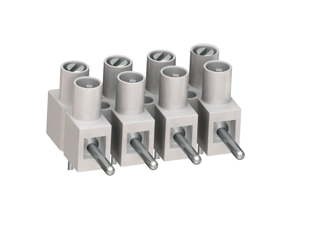
302-SVG
Plug-In Terminal Strip
Screwless connection
DESCRIPTION
The plug-in terminal strip 302-SVG is equipped with a solder pin and designed for the use on PCBs. Due to the small 8 mm pitch, this design is well suited for applications where space is limited. The flexible polyamide moulding can even be mounted on curved surfaces. Used in combination with a plug-in terminal strip 302-FB plug-in terminal strip, the contact pressure is applied by a stainless-steel spring. Plug-in direction is parallel to each other. The wire entrance is located in plug direction. The combination with 302-FLW-DS creates an angular plug connection which is well suited of resolving even challenging mounting conditions. The angular plug-in connector type 302-FLW-DS has a contact spring which forms a unit with the wire protector. The direction of insertion is in a 90° angle. The wire entrance is perpendicular to the direction of insertion. In plugged condition, all metal components are protected against accidental contact, except for the solder pins. The screws are captive, vibration-proof and secured against self-loosening. The strips have fixing holes to attach the screws between the poles. The plug-in connector can be used as three-way contact.
GENERAL INFORMATION
TECHNICAL DATA
Clamping Range:
0.34 - 2.5 mm² / 0.34 - 2.5 mm² / 22 - 14 AWG
Rated cross section: 1.5 mm²
Wire stripping length: 5 mm ± 0.5 mm
Over Voltage Category
III
III
II
Pollution Severity Level
3
2
2
Rated Voltage
400 V
630 V
1000 V
Rated Impulse Voltage
6 kV
6 kV
6 kV
Rated current: 6 A
Rated insulation voltage: 450 V acc. to EN 60998-1
Hole in PCB: ø 1.3 mm
Other specifications: Rated values apply to use in combination with 302-FB(-DS) or 302-FLW-DS.
RATINGS
|
Current [A] |
Voltage [V] |
Group |
AWG |
Torque [Nm] |
|
|---|---|---|---|---|---|

|
300 | 10 | B,D,E | 26 - 12 | 0.4 [1] |
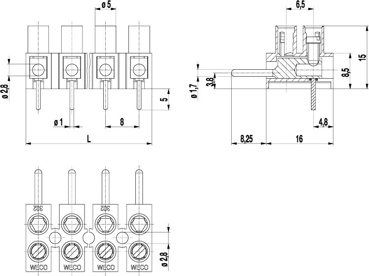
TECHNICAL DRAWINGS
MATERIALS
Moulding: PA, white, V-0
Comparative tracking index: CTI ≥ 600
Insulating group: I
Temperature range: -40°C up to 100°C
Terminal body: Tin plated brass
Screw: M2,6; zinc plated steel, blue passivated_x000D_zinc plated steel, blue passivated
Solder pin: ø 1 mm; tin plated copper
OPTIONS / ACCESSORIES
- Marking strips BST-302
- Longer solder pins up to 75 mm


