

978-EN (-DS)
PCB Connector
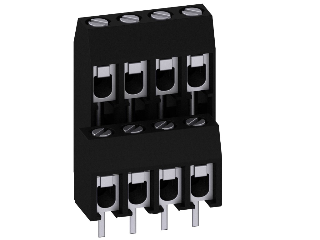
Screw connection, double deck, enlarged clamping area
DESCRIPTION
The PCB connector 978-EN, a two-tier version with larger terminal space and a pitch of 5 mm is available in 4- to 24-pole design. This connector is a combination of the 978-HEN with the 978 version. The rear latching hook on the 978 series locks both terminals to one unit. This configuration allows application-specific locking combinations. The wire protector of the “DS”-version reliably prevents damage to multi-wire flexible conductors by the turning screw.
GENERAL INFORMATION
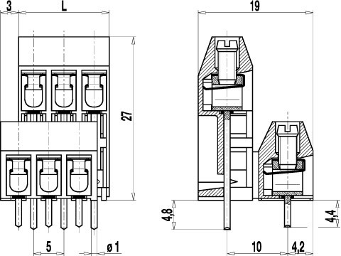
Pitch: 5.00 mm
No. of poles: 4 - 24
TECHNICAL DATA
Clamping Range:
without wire protector
with wire protector:
Rated cross section: 2.5 mm²
Wire stripping length: 6.5 mm ± 0.5 mm
Over Voltage Category
III
III
II
Pollution Severity Level
3
2
2
Rated Voltage
250 V
320 V
630 V
Rated Impulse Voltage
4 kV
4 kV
4 kV
Rated current: 24 A
Rated insulation voltage: 250 V acc. to EN 60998-1
Hole in PCB: ø 1.3 mm
Torque: 0.5 Nm
RATINGS
|
Current [A] |
Voltage [V] |
Group |
AWG |
Torque [Nm] |
|
|---|---|---|---|---|---|

|
20 | 300 | B | 22-12 [1] | 0.51 |
| 10 | 300 | D | 22-12 [1] | 0.51 | |

|
20 | 300 | B | 26 - 12 | 0.51 |
| 10 | 300 | D, E | 26 - 12 | 0.51 |
| Current [A] |
Voltage [V] |
Cross Section [mm2] |
AWG |
TORQUE |
|
|---|---|---|---|---|---|

|
24 | 250 | 4.0 |
TECHNICAL DRAWINGS
MATERIALS
Moulding: PA, grey, V-0
Comparative tracking index: CTI ≥ 600
Insulating group: I
Temperature range: -40°C up to 100°C
Terminal body: Tin plated brass
Screw: M3; zinc plated steel, blue passivated
Solder pin: ø 1 mm; tin plated copper
Wire protector: Tin plated tin bronze
OPTIONS / ACCESSORIES
- Consecutive numbering
- Special marking according to drawing
- Self-adhesive marking strip BST-5,00
- Pitch of 10 mm for larger clearance and creepage distances
- Other solder pin lengths on request
- Double wire protector as bridge
- Cover for the solder pins for additional misplacing and contact protection
- Two-Tier version with the rear row offset to the left
- Special combination of the front and rear row of the two-tier version


