
210-A-121
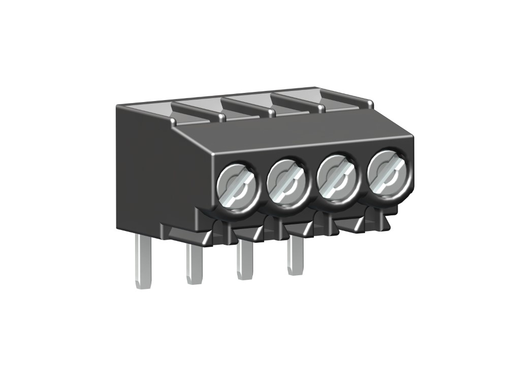
GENERAL INFORMATION
Pitch: 3.50 mm
No. of poles: 2 - 24
TECHNICAL DATA
Clamping Range:
solid / flexible / AWG
0.14 - 1.5 mm² / 0.14 - 1.5 mm² / 30 - 16 AWG
0.14 - 1.5 mm² / 0.14 - 1.5 mm² / 30 - 16 AWG
Rated cross section: 1 mm²
Wire stripping length: 5.5 mm ± 0.5 mm
Over Voltage Category
III
III
II
Pollution Severity Level
3
2
2
Rated Voltage
160 V
160 V
320 V
Rated Impulse Voltage
2.5 kV
2.5 kV
2.5 kV
Rated current: 12.5 A
Rated insulation voltage: 130 V acc. to EN 60998-1
Hole in PCB: ø 1.2 mm
Torque: 0.2 Nm
RATINGS
|
Current [A] |
Voltage [V] |
Group |
AWG |
Torque [Nm] |
|
|---|---|---|---|---|---|

|
10 | 300 | B | 30 - 16 | 0.23 |

|
10 | 300 | B | 30 - 16 | 0.22 |
Download PDF
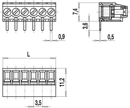
TECHNICAL DRAWINGS
MATERIALS
Moulding: PA, grey, V-0
Comparative tracking index: CTI 400
Insulating group: II
Temperature range: -40°C up to 100°C
Terminal body: Nickel plated brass
Pressure clamp: Copper alloy, tin plated
Screw: M2; copper alloy, tin plated
Solder pin: Copper alloy, tin plated
OPTIONS / ACCESSORIES
- Consecutive numbering
- Special marking according to drawing
- Self-adhesive marking strip BST-3,50


