121-F-111
Plug Connector
Screwless connection

DESCRIPTION
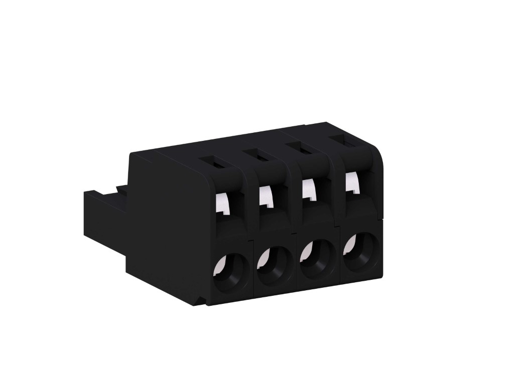
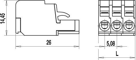
The plug connector 121-F-111 series with screwless terminals complements our “CONECTA”-Series. The rated cross-section of 2,5 mm² is geared towards screw-connector variants. This plug connector can be used with single-core copper conductors and fine-stranded wires (2,5 mm²), but also with pin cable sockets or crimped ferrules. For crimped ferrules, the cross-section must be reduced accordingly. All other rated data is identical with the screw-connector variants. Test ports for ø 2 mm or ø 2,3 mm test plugs or for spring test pins are accessible from the upper side of the clamp. The plug connector consists of individual poles and can be manufactured to any required pole configuration at our factory. For each pole the plug connector has one trapezoidal coding groove in which the coding elements 120-K can be inserted. The plug connector can be operated by either a standard 3 mm blade screwdriver, terminal pliers or the built-in pusher, see 121-F-211.
GENERAL INFORMATION
TECHNICAL DATA
Clamping Range:
0.2 - 4 mm² / 0.2 - 2.5 mm² / 24 - 12 AWG
Rated cross section: 2.5 mm²
Wire stripping length: 8.5 mm ± 0.5 mm
Over Voltage Category
II
Pollution Severity Level
2
Rated Voltage
320 V
Rated Impulse Voltage
2.5 kV
Rated current: 12 A
Rated insulation voltage: 130 V acc. to EN 60998-1
TECHNICAL DRAWINGS

MATERIALS
Moulding: PA, grey, V-0
Comparative tracking index: CTI ≥ 600
Insulating group: I
Temperature range: -40°C up to 100°C
Spring: Copper alloy, tin plated
Pressure clamp: Copper alloy, tin plated
Contact spring: Stainless strip steel
OPTIONS / ACCESSORIES
- Consecutive numbering
- Special marking according to drawing
- Self-adhesive marking strip BST-5,08
- Coding elements 120-K
- Connectors equipped with coding elements on request
- Strain relief
- Terminal pliers 120-F


