

964-T (-DS)
PCB Connector
Screw connection, 45° wire entry, dovetail version

DESCRIPTION
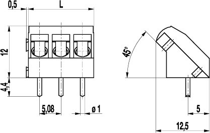
The PCB connector 964-T is the inclined version with a pitch of 5,08 mm and available in 2- and 3 poles. It can be mounted side-by-side without pole loss. Lateral latching elements on the housing allow to latch the PCB connector to longer terminal strips without pole loss. The wire entrance is diagonal, i.e. in a 45° angle to the PC board. Therefore, this PCB connector is ideal for the assembly in the center of PCBs. The design of this PCB connector allows space-saving arrangement of consecutive rows of terminals. Wire protection in DS-design reliably prevents damage to stranded wires by the screw. The screws are secured against self-loosening. For the grid connection, these PCB connectors are equipped with a M3 thread.
GENERAL INFORMATION
Pitch: 5.08 mm
No. of poles: 2 + 3
TECHNICAL DATA
Clamping Range:
without wire protector
with wire protector:
Rated cross section: 2.5 mm²
Wire stripping length: 6.5 mm
Over Voltage Category
III
III
II
Pollution Severity Level
3
2
2
Rated Voltage
250 V
320 V
630 V
Rated Impulse Voltage
4 kV
4 kV
4 kV
Rated current: 24 A
Rated insulation voltage: 250 V acc. to EN 60998-1
Hole in PCB: ø 1.3 mm
Torque: 0.5 Nm
RATINGS
|
Current [A] |
Voltage [V] |
Group |
AWG |
Torque [Nm] |
|
|---|---|---|---|---|---|

|
20 | 300 | B | 22-12 [1] | 0.51 |
| 10 | 300 | D | 22-12 [1] | 0.51 | |

|
20 | 300 | B | 26 - 12 | 0.51 |
| 10 | 300 | D, E | 26 - 12 | 0.51 |
TECHNICAL DRAWINGS
MATERIALS
Moulding: PA, grey, V-0
Comparative tracking index: CTI ≥ 600
Insulating group: I
Temperature range: -40°C up to 100°C
Terminal body: Tin plated brass
Screw: M3; zinc plated steel, clear passivated
Solder pin: ø 1 mm; tin plated copper
Wire protector: Tin plated tin bronze
OPTIONS / ACCESSORIES
- CN: Consecutive Numbering
- SM: Special Marking (please provide sketch)
- G05: Gold Plating (5 micro inches)
- G30: Gold Plating (30 micro inches)
- S30: Silver Plating (30 micro inches)
- Self-Adhesive marking strip BST-5.08
- Can be snapped together to larger pole version
- Different pin lengths
- 970-J1, Jumper


