

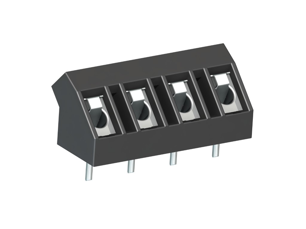
976 (-DS)
PCB Connector
Screw connection, 45° wire entry
DESCRIPTION
The PCB connector 976, inclined version with a pitch of 7,5 mm is available with 2 and 3 poles and can be mounted side-by-side in the nominal pitch. Due to their large clearance and creepage distances, these PCB connectors are particularly suitable for higher voltages. The wire entrance is in a 45° angle diagonal to the PC board. Therefore, this PCB connector is ideal for the assembly in the center of PCBs. The design of this PCB connector allows space-saving arrangement of consecutive rows of terminals. Wire protection in DS-design reliably prevents damage to stranded wires by the screw.
GENERAL INFORMATION
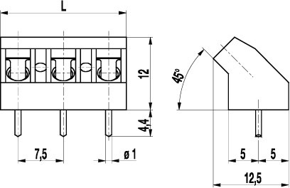
Pitch: 7.50 mm
No. of poles: 2 + 3
TECHNICAL DATA
Clamping Range:
without wire protector
with wire protector:
Rated cross section: 2.5 mm²
Wire stripping length: 6.5 mm ± 0.5 mm
Over Voltage Category
III
III
II
Pollution Severity Level
3
2
2
Rated Voltage
400 V
630 V
1000 V
Rated Impulse Voltage
6 kV
6 kV
6 kV
Rated current: 24 A
Rated insulation voltage: 750 V acc. to EN 60998-1
Hole in PCB: ø 1.3 mm
Torque: 0.5 Nm
RATINGS
|
Current [A] |
Voltage [V] |
Group |
AWG |
Torque [Nm] |
|
|---|---|---|---|---|---|

|
15 | 300 | B | 22-12 [1] | 0.51 |

|
20 | 300 | B | 26 - 12 | 0.51 |
| 10 | 300 | D, E | 26 - 12 | 0.51 |
| Current [A] |
Voltage [V] |
Cross Section [mm2] |
AWG |
TORQUE |
|
|---|---|---|---|---|---|

|
24 | 750 | 2.5 |
TECHNICAL DRAWINGS
MATERIALS
Moulding: PA, grey, V-0
Comparative tracking index: CTI ≥ 600
Insulating group: I
Temperature range: -40°C up to 100°C
Terminal body: Tin plated brass
Screw: M3; zinc plated steel, clear passivated
Solder pin: ø 1 mm; tin plated copper
Wire protector: Tin plated tin bronze
OPTIONS / ACCESSORIES
- Consecutive numbering
- Special marking according to drawing
- Self-adhesive marking strip BST-7,50
- Longer solder pins up to 95 mm
- Special wire protector for very thin conductors
- Version with raised foot of 1,6 mm


