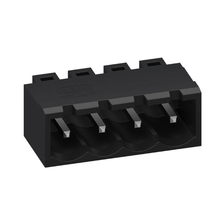
121-ME-211

Header

Plug-in direction parallel to PCB

121-ME-211-R.jpg

ALLGEMEINE DATEN

Raster: 5.08 mm

Polzahlen: 2 - 24

Verwendbar mit: 121-FEP-311

TECHNISCHE DATEN

Bemessungsstoßspannung

4 kV

Bemessungsstrom: 16 A

Bemessungsisolationsspannung: 250 V

Bohrung in der Leiterplatte: ø 1.5 mm

ZULASSUNGEN

Strom
[A]
Spannung
[V]
Gruppe
 
AWG
 
Drehmoment
[Nm]
16 300 B, D
PDF herunterladen

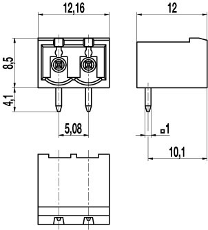
TECHNISCHE ZEICHNUNGEN

121-ME-211.jpg - technical drawing 1

MATERIALDATEN

Gehäusematerial: PA V0, black

Temperaturgrenzen: -40°C up to 130°C

Lötstift: 1.0 x 1.0 mm; tin-plated copper alloy

SONDERAUSFÜHRUNG / ZUBEHÖR

  • Consecutive numbering
  • Coding elements

AUSFÜHRUNGEN

Pole Artikel Artikelnummer # Länge L [mm] Step 3D PDF
02 121-ME-211/02 10.806.982 12.16
03 121-ME-211/03 10.806.983 17.24
04 121-ME-211/04 10.806.984 22.32
05 121-ME-211/05 10.806.985 27.40
06 121-ME-211/06 10.806.986 32.48
07 121-ME-211/07 10.806.987 37.56
08 121-ME-211/08 10.806.988 42.64
09 121-ME-211/09 10.806.989 47.72
10 121-ME-211/10 10.806.990 52.80
11 121-ME-211/11 10.806.991 57.88
12 121-ME-211/12 10.806.992 62.96

Did you find the information you were looking for ?

Click on a star to rate your experience.

Average rating 0 / 5. Vote count: 0

No votes so far! Be the first to rate this post.