

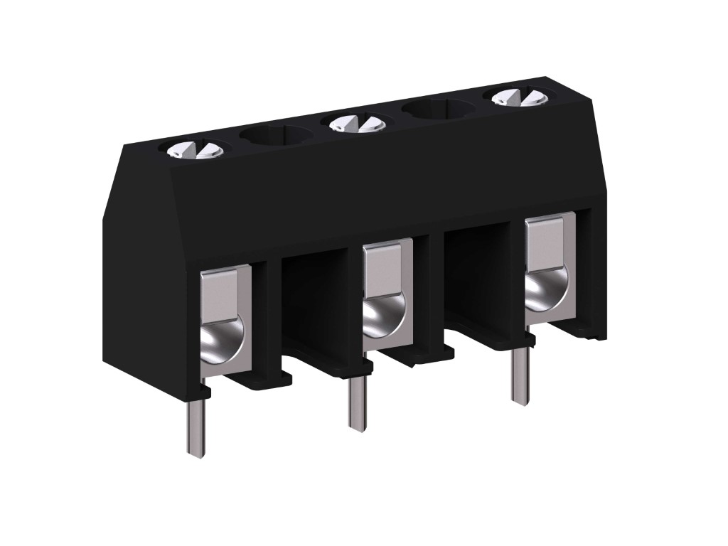
972 (-DS)
PCB Connector
Screw connection
BESCHREIBUNG
The PCB connector 972 with a pitch of 10 mm is available in 2- to 16-pole design and has large clearance and creepage distances. Wire protection in DS-design reliably prevents damage to stranded wires by the screw. The screws are secured against self-loosening.
ALLGEMEINE DATEN
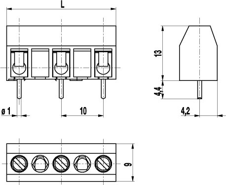
Raster: 10.00 mm
Polzahlen: 2 - 16
TECHNISCHE DATEN
Spannbereich:
ohne Drahtschutz
mit Drahtschutz:
Nennquerschnitt: 2.5 mm²
Abisolierlänge: 6.5 mm ± 0.5 mm
Überspannungskategorie
III
III
II
Verschmutzungsgrad
3
2
2
Bemessungsspannung
630 V (500 V)
630 V
1000 V
Bemessungsstoßspannung
6 kV
6 kV
6 kV
Bemessungsstrom: 24 A
Bohrung in der Leiterplatte: ø 1.3 mm
Drehmoment: 0.5 Nm
Andere Spezifikationen: Rated voltage in brackets applies to 5-16-pole connectors, “no-flame” according to glow wire test applies to 2-4-pole connectors.
ZULASSUNGEN
|
Strom [A] |
Spannung [V] |
Gruppe |
AWG |
Drehmoment [Nm] |
|
|---|---|---|---|---|---|

|
20 | 300 | B | 22-12 [1] | 0.51 |
| 20 | 150 | C | 22-12 [1] | 0.51 | |

|
20 | 300 | B | 26 - 12 | 0.51 |
| 10 | 300 | D, E | 26 - 12 | 0.51 |
| Aktuell [A] |
Spannung [V] |
Querschnitt [mm2] |
AWG |
DREHMOMENT |
|
|---|---|---|---|---|---|

|
24 | 750 | 2.5 |
TECHNISCHE ZEICHNUNGEN
MATERIALDATEN
Gehäusematerial: PA, grey, V-0
Kriechstromfestigkeit: 2-4 poles: CTI ≥ 600; 5-16 poles: CTI 400
Isolierstoffgruppe: 2-4 poles: I; 5-16 poles: II
Temperaturgrenzen: -40°C up to 100°C
Klemmkörper: Tin plated brass
Schraube: M3; zinc plated steel, blue passivated
Lötstift: ø 1 mm; tin plated copper alloy
Drahtschutz: Tin plated tin bronze
SONDERAUSFÜHRUNG / ZUBEHÖR
- Consecutive numbering
- Special marking according to drawing
- Self-adhesive marking strip BST-10,00
- Longer solder pins up to 95 mm
- Two solder pins per pole, please see 978-TY(-DS) in 5 mm pitch
- Version with extended wire entrance
- Version with larger clamping range


