WECO’s unique patented technology of surface mount devices are capable of handling a maximum current range from 8 A to 17.5 A, an enhanced IoT power connector with floating pin technology.
Discover WECO’s compact Surface Mount
PowerTerminal Blocks for high current!
SMarTconn connectors
We’ve solved the challenges of soldering larger power terminal blocks
With IoT, the need for innovative connection solutions have flourished as control boards have shrunk in size resulting in increased power distribution over smaller and densely populated PCB’s. Learn how WECO addressed these challenges with our “floating pin” technology. Soldering larger power terminal blocks using SMT reflow processes poses several challenges in the manufacturing environment.
WECO’s floating pin technology is designed to ensure a sound connection to the host PCB and a high “peel-off” force for these large surface-mount-devices. The design considers key parameters such as: size, weight, coplanarity of a larger device relative to the PCB and coefficient of thermal expansion between the connectors and PCB.
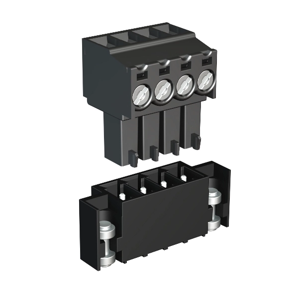
Whether you’re working with direct wire-to-board or using a two-piece with header or pin-strip soldered to board, WECO can help you overcome these common issues.
#1
Paste thickness (solder pad)
Soldering a mix of large and small SMD using the same paste thickness to ensure a secure solder joint, when large components require a larger solder pad and a thicker layer.
#2
Coefficient of Thermal Expansion
Dealing with components of varying size, shape, material, and weight, all of which have different CTE (Coefficient of Thermal Expansion) and expand at different rates compared to smaller semiconductors.
#3
Coplanarity
Coplanarity, which is defined as the maximum distance between a surface-mount device (SMD) and its seating plane (the PCB). For large components such as power terminal blocks, the “package coplanarity” is often higher, meaning there is a greater variance between the seating plane of the terminal block and the PCB.
This specialized series of terminal blocks is designed with floating elements. How can they help?
Each contact is independent and able to “float“ within the terminal body, ensuring coplanarity with the PCB surface. The principle of a floating contact allows proper alignment to the PCB as the capillary action of the solder paste aligns each contact independently, eliminating the CTE mismatch during the reflow process.
Our unique patent ensures consistent alignment of our connectors to the PCB solder pads.
#1
Allowing the contact to float and self-align with the solder mask.
This principle of a floating elements allows an independent alignment of each contact to the PCB solder pads ensuring coplanarity as well as ensuring a proper capillary action of the solder paste to “wick-up” and position each contact independently and therefore eliminating the CTE (coefficient of thermal expansion) mismatch during the reflow process.
Having components of various sizes requires selectively increasing the solder paste thickness where larger components are placed. However, this is often a challenge due to time constraints and can be difficult to achieve in a production environment. If the solder paste is too thick, there is a high probability of solder bridging for fine pitch components.
#2
Compensating for Dealing with Coefficient of Thermal Expansion – (CTE)
Aligning each contact to the PCB, ensuring coplanarity with the PCB surface, and ensuring a proper capillary action of the solder paste to wet and position each contact independently and eliminate the CTE mismatch during the reflow process. The pins float and make contact with the PCB.
#3
Ensuring the leads contact the solder paste in a consistent manner
Excellent coplanarity is required to successfully solder components to a typical PCB, to which paste has been applied using a 0.125 mm (5 mil) stencil. The leads must contact the solder paste in a consistent manner for the reflow process to work well. Excellent coplanarity increases the soldering process yields (a low rate of open circuits), increases solder joint strength (robustness to human factors and inferred fatigue reliability), and promotes in-field solder joint reliability (better fatigue performance in thermal cycling). IPC SM 785 Guidelines for Accelerated Reliability Testing for Surface Mount.
A proven solution
WECO’s SMarTconn is a portfolio of patented, field-tested, and robust connectors, terminal blocks, pins and anchors with floating elements (or contacts) specifically designed for advanced SMT processes.
-
Optimal Total Cost of Ownership (TCO)
-
Overall cost savings
-
Increased Real Estate on the PCB
-
Reliable
-
Eliminate CTE mismatch
-
Robust
-
Self-alignment of the contact elements through natural cohesion
WECO testing phases and proven results of the SMarTconn
Summary of the test report
Test plans were established to calculate and measure the long-term reliability of the soldered connections and the retention of the larger power terminal block to the PCB. The design considers the “Peel-Off Force”, “Pull-Out-Force” and “Torque Resistance”. For a Peel-Off test, the connector is pulled vertically (perpendicular to the PCB) and used to simulate the resistance on the “Z” shape contacts and PCB solder. Recorded values with a 45º bending of the pins with a force of 18N (for a 4 pole – smaller 110-M-SMD series) resulted in no solder joint damage. Pull-Out-Force consists of pulling the complete housing vertically which simulates the resistance of the header to the pull-out-force generated by a mating plug. The header can be stressed to 180 N for a 4 pole and to 200N for a 12 pole (smaller 110-M-SMD series) until the housing is separated for the pins with no damage to the pin solder joints. Torque resistance measures the robustness of the interface between the PCB solder pads and connector contacts. Connectors can be stressed over 50% higher than the torque applied to the screws securing the wires in the housings.