

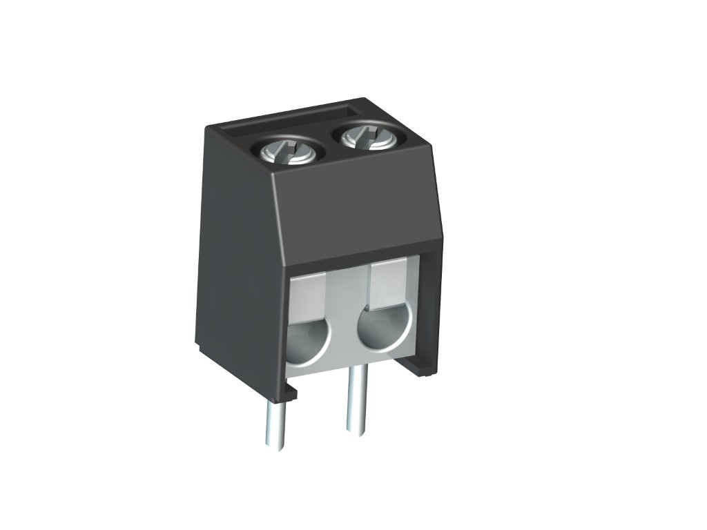
970-X (-DS)
PCB Connector
Screw connection, 2 to 12 screw common connection
DESCRIPTION
The PCB screw connector 970-X.. with a “pitch" of 5 mm has 2 to 12 screw connections at only one pole and can be used e.g. as potential distributors. This allows to loop through earth conductors easily. Wire protection in DS-design reliably prevents damage to stranded wires by the screw. A latchable version with 2 to 4 screw connections at one pole is available as type 970-TX.. NOTE: The pole numbers indicated in the article number do not designate the actual number of poles but the number of screw connections instead!
GENERAL INFORMATION
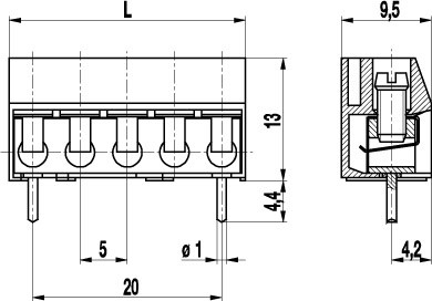
Pitch: 5.00 mm
No. of poles: 1
TECHNICAL DATA
Clamping Range:
without wire protector
with wire protector:
Rated cross section: 2.5 mm²
Wire stripping length: 6.5 mm ± 0.5 mm
Over Voltage Category
III
III
II
Pollution Severity Level
3
2
2
Rated Voltage
250 V
320 V
630 V
Rated Impulse Voltage
4 kV
4 kV
4 kV
Rated current: 24 A
Rated insulation voltage: 250 V acc. to EN 60998-1
Hole in PCB: ø 1.3 mm
Torque: 0.5 Nm
RATINGS
|
Current [A] |
Voltage [V] |
Group |
AWG |
Torque [Nm] |
|
|---|---|---|---|---|---|

|
20 | 300 | B | 22-12 [1] | 0.51 |
| 10 | 300 | D | 22-12 [1] | 0.51 | |

|
20 | 300 | B | 26 - 12 | 0.51 |
| 10 | 300 | D, E | 26 - 12 | 0.51 |
| Current [A] |
Voltage [V] |
Cross Section [mm2] |
AWG |
TORQUE |
|
|---|---|---|---|---|---|

|
24 | 400 | 2.5 |
TECHNICAL DRAWINGS
MATERIALS
Moulding: PA, grey, V-0
Comparative tracking index: CTI ≥ 600
Insulating group: I
Temperature range: -40°C up to 100°C
Terminal body: Tin plated brass
Screw: M3; zinc plated steel, blue passivated
Solder pin: ø 1 mm; tin plated copper
Wire protector: Tin plated tin bronze
OPTIONS / ACCESSORIES
- CN: Consecutive Numbering
- SM: Special Marking (please provide sketch)
- G05: Gold Plating (5 micro inches)
- G30: Gold Plating (30 micro inches)
- S30: Silver Plating (30 micro inches)
- Self-Adhesive marking strip BST-5.00
- Different pin lengths


