

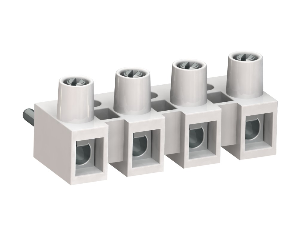
322-D-SV (-DS)
Plug-In Terminal Strip
Screw connection, enlarged clamping area
DESCRIPTION
The 322-D-SV is based on our established plug-in terminal strip 322-SV. The clamping space is enlarged for 2x2,5 mm² solid wire without wire protector or 2x1,5 mm² with wire protector. Therefore, this version is most suitable when connections of two wires per pole are required. With the exception of the clamping system, the measurements conform to the standard design. The screws have a slotted, as well as a cross slot (plus-minus screw) In combination with the plug-in terminal strip 323-FB, this connector provides the contact pressure via a stainless steel spring which ensures good electrical contact. Plug-in direction is parallel to each other. The wire protector of the “DS”-version reliably prevents damage to multi-wire flexible conductors by the turning screw. These terminals strips can be screw-mounted on a substrate.
GENERAL INFORMATION
TECHNICAL DATA
Clamping Range:
without wire protector
with wire protector:
Rated cross section: 2 x 2.5 mm²
Wire stripping length: 7 mm ± 0.5 mm
Over Voltage Category
III
III
II
Pollution Severity Level
3
2
2
Rated Voltage
500 V (160V)
630 V (160V)
1000 V (320V)
Rated Impulse Voltage
6 kV (2.5 kV)
6 kV (2.5 kV)
6 kV (2.5 kV)
Rated current: 16 A. with ambient temperature up to 30°C
Rated insulation voltage: 750 V acc. to EN 60998-1 [1]
Torque: 0.5 Nm
Other specifications: Rated values apply to use in combination with 323-FB(-HDS). Values in parentheses apply to use without insulated substrates.
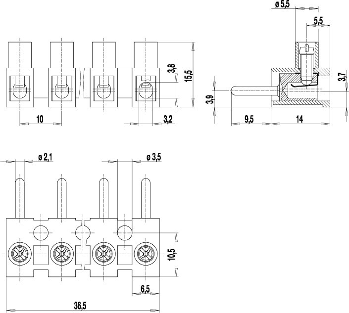
TECHNICAL DRAWINGS
MATERIALS
Moulding: PA, natural, V-2
Comparative tracking index: CTI ≥ 600
Insulating group: I
Temperature range: -40°C up to 100°C
Terminal body: Tin plated brass
Screw: M3; zinc plated steel, blue passivated
Wire protector: Tin plated tin bronze
OPTIONS / ACCESSORIES
- Marking options on and between the screw guides
- Special marking according to drawing
- Jumper 323-J
- G30: Gold Plating (30 micro inches)


