

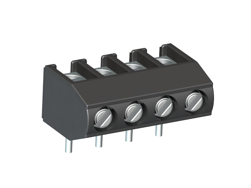
961 (-DS)
PCB Connector
Screw connection, vertical wire entry
DESCRIPTION
The PCB connector 961 is the horizontal version of 960 with a pitch of 5,08 mm and available in 2- to 32-pole design. It can be mounted side-by-side without pole loss. The wire entrance is vertical to the PCB. Compared to the smaller PCB connector 941, it has a larger clamping range and larger clearance and creepage distances. Wire protection in DS-design reliably prevents damage to stranded wires by the screw. The screws are secured against self-loosening. For the grid connection, these PCB connectors are equipped with a M3 thread.
GENERAL INFORMATION
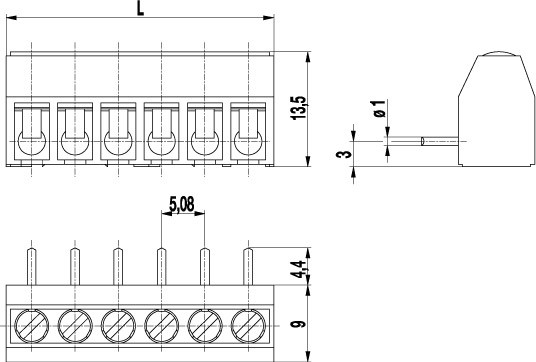
Pitch: 5.08 mm
No. of poles: 2 - 32
TECHNICAL DATA
Clamping Range:
without wire protector
with wire protector:
Rated cross section: 2.5 mm²
Wire stripping length: 5.5 mm ± 0.5 mm
Over Voltage Category
III
III
II
Pollution Severity Level
3
2
2
Rated Voltage
250 V
320 V
630 V (500 V)
Rated Impulse Voltage
4 kV
4 kV
4 kV
Rated current: 24 A
Rated insulation voltage: 250 V acc. to EN 60998-1
Hole in PCB: ø 1.3 mm
Torque: 0.5 Nm
Other specifications: Voltage data in brackets are valid for 9-32 poles types. 2-8 poles types: "no-flame" acc. to glow-wire test.
RATINGS
|
Current [A] |
Voltage [V] |
Group |
AWG |
Torque [Nm] |
|
|---|---|---|---|---|---|

|
20 | 300 | B | 22-12 [1] | 0.51 |
| 10 | 300 | D | 22-12 [1] | 0.51 | |

|
20 | 300 | B | 26 - 12 | 0.51 |
| 10 | 300 | D, E | 26 - 12 | 0.51 |
| Current [A] |
Voltage [V] |
Cross Section [mm2] |
AWG |
TORQUE |
|
|---|---|---|---|---|---|

|
24 | 400 | 2.5 |
TECHNICAL DRAWINGS
MATERIALS
Moulding: PA, grey, V-0
Comparative tracking index: 2-8 poles: CTI ≥ 600; 9-32 poles: CTI 400
Insulating group: 2-8 poles: I; 9-32 poles: II
Temperature range: -40°C up to 100°C
Terminal body: Tin plated brass
Screw: M3; zinc plated steel, blue passivated
Solder pin: ø 1 mm; tin plated brass
Wire protector: Tin plated tin bronze
OPTIONS / ACCESSORIES
- Consecutive numbering
- Special marking according to drawing
- Self-adhesive marking strip BST-5,08
- Version with extended wire entrance
- Double wire protector as bridge


