

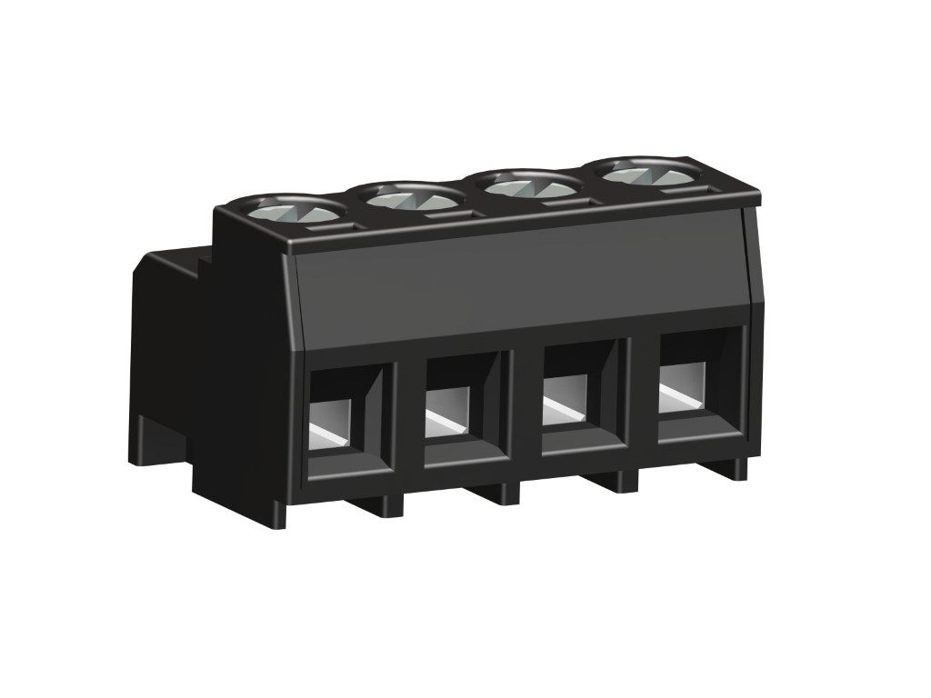
115-F-111
Plug Connector
Screw connection
GENERAL INFORMATION
Pitch: 5.00 mm
No. of poles: 2 - 12
Usable with: plugs with ø 1.3 mm pin 971-SLR series
Application: Building and telecommunication technology, particularly for mass-production applications where space is limited.
TECHNICAL DATA
Clamping Range:
0.14 - 2.5 mm² / 0.14 - 1.5 mm² / 26 - 14 AWG
Rated cross section: 1.5 mm²
Wire stripping length: 6 mm ± 0.5 mm
Over Voltage Category
III
III
II
Pollution Severity Level
3
2
2
Rated Voltage
250 V
320 V
630 V
Rated Impulse Voltage
4 kV
4 kV
4 kV
Rated current: 10 A
Rated insulation voltage: 250 V acc. to EN 60998-1
Torque: 0.5 Nm
RATINGS
|
Current [A] |
Voltage [V] |
Group |
AWG |
Torque [Nm] |
|
|---|---|---|---|---|---|

|
12 | 300 | B | 26 - 14 | 0.23 |
| 10 | 300 | D | 26 - 14 | 0.23 | |

|
12 | 300 | B | 26 - 14 | 0.22 |
| 10 | 300 | D, E | 26 - 14 | 0.22 |
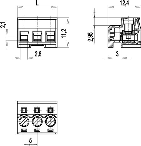
TECHNICAL DRAWINGS
MATERIALS
Moulding: PA, grey, V-0
Comparative tracking index: CTI ≥ 600
Insulating group: I
Temperature range: -40°C up to 100°C
Terminal body: Nickel plated brass
Spring: Copper alloy, tin plated
Pressure clamp: Copper alloy, tin plated
Screw: M3; zinc plated steel, blue passivated
OPTIONS / ACCESSORIES
- Consecutive numbering
- Special marking according to drawing
- Self-adhesive marking strip BST-5,00


