

115-F-118/..-1.1-SW
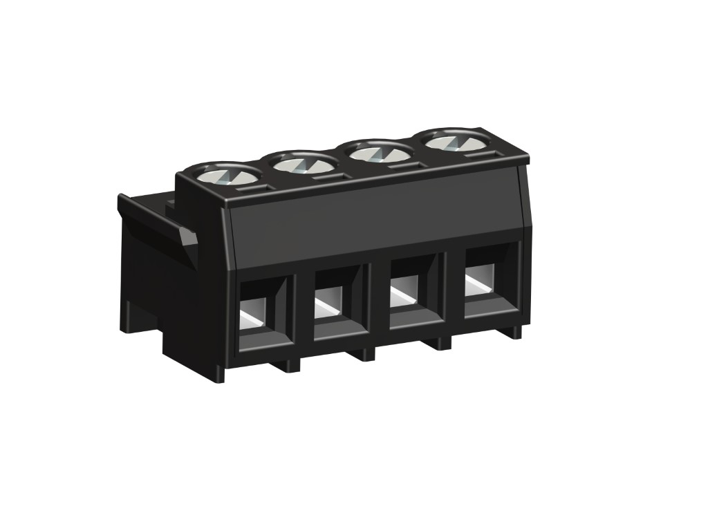
Plug Connector
Screw connection, with lateral ribs
DESCRIPTION
Especially for our pin strips with pin diameter 1,1 mm this plug connector 115-F-118/..1,1-SW was developed. Except for the colour and special spring the connector is identical with the version 115-F-118. Series 115-F-118/..1,1-SW features lateral ribs on both sides, which snap-in the housing’s latching hook, thus ensuring optimum tight fit. PCBs are usually connected with the pin strips from above. The housing consits of a black polyamide (addition "-SW" in the product description), to differ this one from the grey version 115-F-118. Application example - thermostat housing: The plug connectors are snapped in the basic housing and their leads are wired externally. Subsequently, the control panel, equipped with corresponding pin strips, is connected from above.
GENERAL INFORMATION
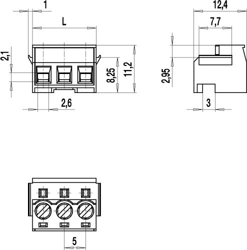
Pitch: 5.00 mm
No. of poles: 2 - 12
Usable with: plugs with ø 1.1 mm pin 971-SLR, SLT pinstrip series
Application: Building and telecommunication technology, particularly for mass-production applications where space is limited.
TECHNICAL DATA
Clamping Range:
0.14 - 2.5 mm² / 0.14 - 1.5 mm² / 26 - 14 AWG
Rated cross section: 1.5 mm²
Wire stripping length: 6 mm ± 0.5 mm
Over Voltage Category
III
III
II
Pollution Severity Level
3
2
2
Rated Voltage
250 V
320 V
630 V
Rated Impulse Voltage
4 kV
4 kV
4 kV
Rated current: 10 A
Rated insulation voltage: 250 V acc. to EN 60998-1
Torque: 0.5 Nm
RATINGS
|
Current [A] |
Voltage [V] |
Group |
AWG |
Torque [Nm] |
|
|---|---|---|---|---|---|

|
12 | 300 | B | 26 - 14 | 0.23 |
| 10 | 300 | D | 26 - 14 | 0.23 | |

|
300 | 12 | B | 26 - 14 | 0.22 |
| 10 | D, E | 26 - 14 | 0.22 |
TECHNICAL DRAWINGS
MATERIALS
Moulding: PA, black, V-0
Comparative tracking index: CTI ≥ 600
Insulating group: I
Temperature range: -40°C up to 100°C
Terminal body: Nickel plated brass
Spring: Copper alloy, tin plated
Pressure clamp: Copper alloy, tin plated
Screw: M3; zinc plated steel, blue passivated
OPTIONS / ACCESSORIES
- Consecutive numbering
- Special marking according to drawing
- Self-Adhesive marking strip BST-5.00


