

120-D-115
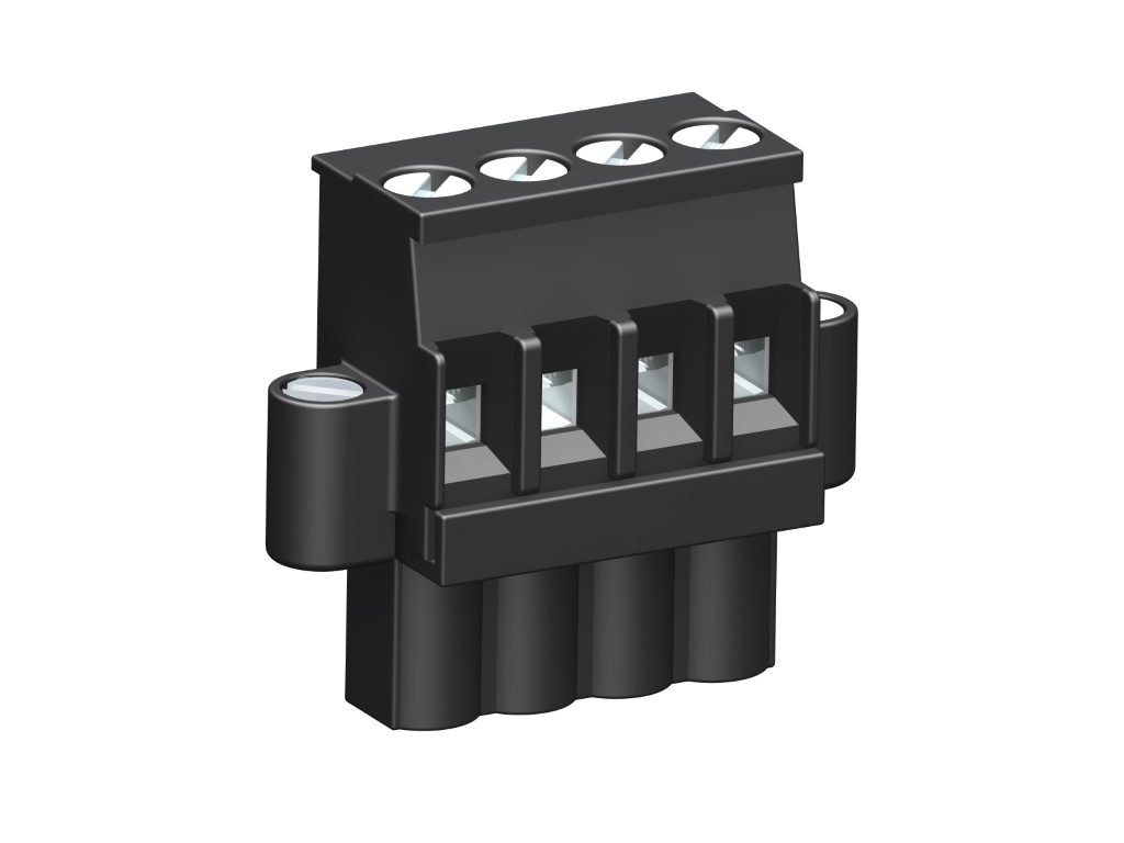
Plug Connector
Screw connection, backside latching hooks, with connecting flanges
GENERAL INFORMATION
TECHNICAL DATA
Clamping Range:
solid / flexible / AWG
0.2 - 4 mm² / 0.2 - 2.5 mm² / 26 - 12 AWG
0.2 - 4 mm² / 0.2 - 2.5 mm² / 26 - 12 AWG
Wire stripping length: 7 mm ± 0.5 mm
Over Voltage Category
III
III
II
Pollution Severity Level
3
2
2
Rated Voltage
250 V
320 V
630 V
Rated Impulse Voltage
4 kV
4 kV
4 kV
Rated current: 12 A
Rated insulation voltage: 250 V acc. to EN 60998-1
Torque: 0.5 Nm
RATINGS
|
Current [A] |
Voltage [V] |
Group |
AWG |
Torque [Nm] |
|
|---|---|---|---|---|---|

|
15 | 300 | B | 26 - 12 | 0.51 |
| 10 | 300 | D | 26 - 12 | 0.51 | |

|
15 | 300 | B | 26 - 12 | 0.51 |
| 10 | 300 | D, E | 26 - 12 | 0.51 |
Download PDF
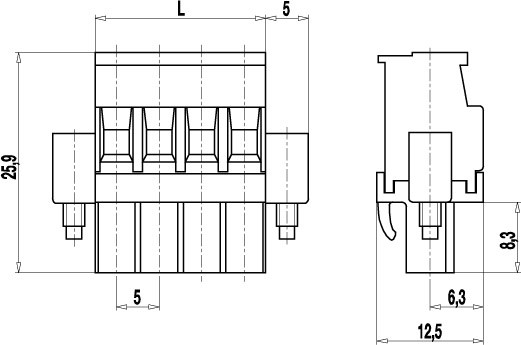
TECHNICAL DRAWINGS
MATERIALS
Moulding: PA, grey, V-0
Comparative tracking index: CTI ≥ 600
Insulating group: I
Temperature range: -40°C up to 100°C
Terminal body: Nickel plated brass
Spring: Tin plated tin bronze
Pressure clamp: Tin plated tin bronze
Screw: M3; zinc plated steel, blue passivated
OPTIONS / ACCESSORIES
- Consecutive numbering
- Special marking according to drawing
- Self-adhesive marking strip BST-5,00
- Pitch of 10 mm for larger clearance and creepage distances
- Coding elements 120-K
- Connectors equipped with coding elements on request
- Strain relief


