

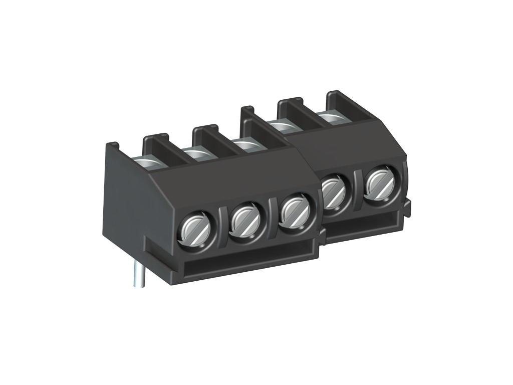
961-T (-DS)
PCB Connector
Screw connection, vertical wire entry, dovetail version
DESCRIPTION
The PCB connector 961-T is the horizontal version of 960-T with a pitch of 5,08 mm and available in 2 and 3 poles. It can be mounted side-by-side without pole loss. Compared to the smaller PCB connector 941-T, it has a larger clamping range and larger clearance and creepage distances. Lateral latching elements on the housing allow to latch the PCB connector to longer terminal strips without pole loss. The wire entrance is vertical to the PCB. Wire protection in DS-design reliably prevents damage to stranded wires by the screw. The screws are secured against self-loosening. For the grid connection, these PCB connectors are equipped with a M3 thread.
GENERAL INFORMATION
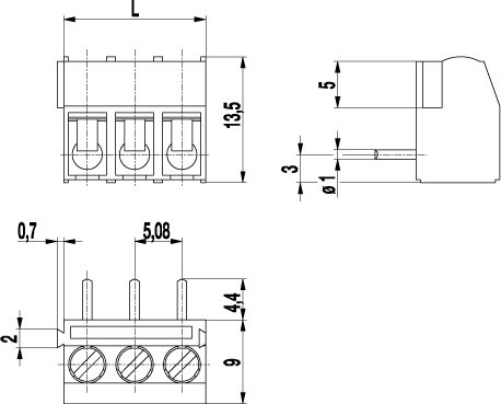
Pitch: 5.08 mm
No. of poles: 2 + 3
TECHNICAL DATA
Clamping Range:
without wire protector
with wire protector:
Rated cross section: 2.5 mm²
Wire stripping length: 5.5 mm ± 0.5 mm
Over Voltage Category
III
III
II
Pollution Severity Level
3
2
2
Rated Voltage
250 V
320 V
630 V
Rated Impulse Voltage
4 kV
4 V
4 kV
Rated current: 24 A
Rated insulation voltage: 250 V acc. to EN 60998-1
Hole in PCB: ø 1.3 mm
Torque: 0.5 Nm
RATINGS
|
Current [A] |
Voltage [V] |
Group |
AWG |
Torque [Nm] |
|
|---|---|---|---|---|---|

|
20 | 300 | B | 22-12 [1] | 0.51 |
| 10 | 300 | D | 22-12 [1] | 0.51 | |

|
20 | 300 | B | 26 - 12 | 0.51 |
| 10 | 300 | D, E | 26 - 12 | 0.51 |
| Current [A] |
Voltage [V] |
Cross Section [mm2] |
AWG |
TORQUE |
|
|---|---|---|---|---|---|

|
24 | 400 | 2.5 |
TECHNICAL DRAWINGS
MATERIALS
Moulding: PA, grey, V-0
Comparative tracking index: CTI ≥ 600
Insulating group: I
Temperature range: -40°C up to 100°C
Terminal body: Tin plated brass
Screw: M3; zinc plated steel, blue passivated
Solder pin: ø 1 mm; tin plated brass
Wire protector: Tin plated tin bronze
OPTIONS / ACCESSORIES
- Consecutive numbering
- Special marking according to drawing
- Self-adhesive marking strip BST-5,08
- Longer solder pins up to 75 mm
- Version with extended wire entrance
- Double wire protector as bridge


