

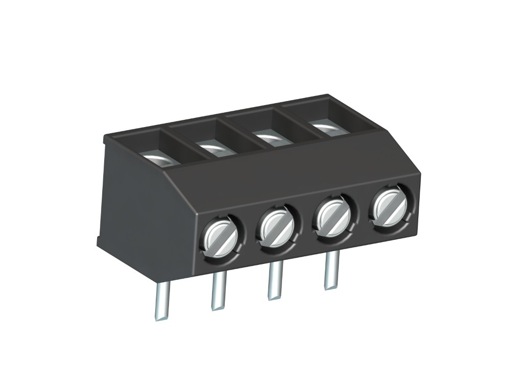
971-HG (-DS)
PCB Connector
Screw connection, vertical wire entry, extended insertion length
DESCRIPTION
The PCB connector 971-HG with a pitch of 5 mm is available in 2- to 32-pole design and can be mounted side-by-side without pole loss. On this PCB connector the copper solder pin is welded on top of the socket bore. This expands the insertion length to series 970 socket depth and allows to use extra-long solder pins. Wire protection in DS-design reliably prevents damage to stranded wires by the screw. The wire entrance is vertical to the PCB.
GENERAL INFORMATION
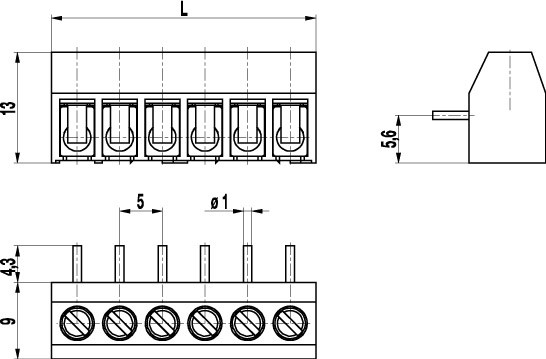
Pitch: 5.00 mm
No. of poles: 2 - 32
TECHNICAL DATA
Clamping Range:
without wire protector
with wire protector:
Rated cross section: 2.5 mm²
Wire stripping length: 6.5 mm ± 0.5 mm
Over Voltage Category
III
III
II
Pollution Severity Level
3
2
2
Rated Voltage
250 V (200 V)
320 V
630 V (400 V)
Rated Impulse Voltage
4 kV
4 kV
4 kV
Rated current: 24 A
Rated insulation voltage: 250 V acc. to EN 60998-1
Hole in PCB: ø 1.3 mm
Torque: 0.5 Nm
Other specifications: Voltage data in brackets are valid for 9-32 poles types. 2-8 poles types are "no-flame" acc. to glow-wire test.
RATINGS
|
Current [A] |
Voltage [V] |
Group |
AWG |
Torque [Nm] |
|
|---|---|---|---|---|---|

|
20 | 300 | B | 22-12 [1] | 0.51 |
| 10 | 300 | D | 22-12 [1] | 0.51 | |

|
20 | 300 | B | 26 - 12 | 0.51 |
| 10 | 300 | D, E | 26 - 12 | 0.51 |
| Current [A] |
Voltage [V] |
Cross Section [mm2] |
AWG |
TORQUE |
|
|---|---|---|---|---|---|

|
24 | 400 | 2.5 |
TECHNICAL DRAWINGS
MATERIALS
Moulding: PA, grey, V-0
Comparative tracking index: 2-8 poles: CTI ≥ 600; 9-32 poles: CTI 400
Insulating group: 2-8 poles: I; 9-32 poles: II
Temperature range: -40°C up to 100°C
Terminal body: Tin plated brass
Screw: M3; zinc plated steel, blue passivated
Solder pin: ø 1 mm; tin plated copper
Wire protector: Tin plated tin bronze
OPTIONS / ACCESSORIES
- Consecutive numbering
- Special marking according to drawing
- Self-adhesive marking strip BST-5,00
- Pitch 10 mm for larger clearance and creepage distances
- Longer solder pins up to 75 mm
- Version with extended wire entrance
- Version with larger clamping range
- Double wire protector as bridge
- With test holes, see 971-HM(-DS)


