

974-D-SMD-DS
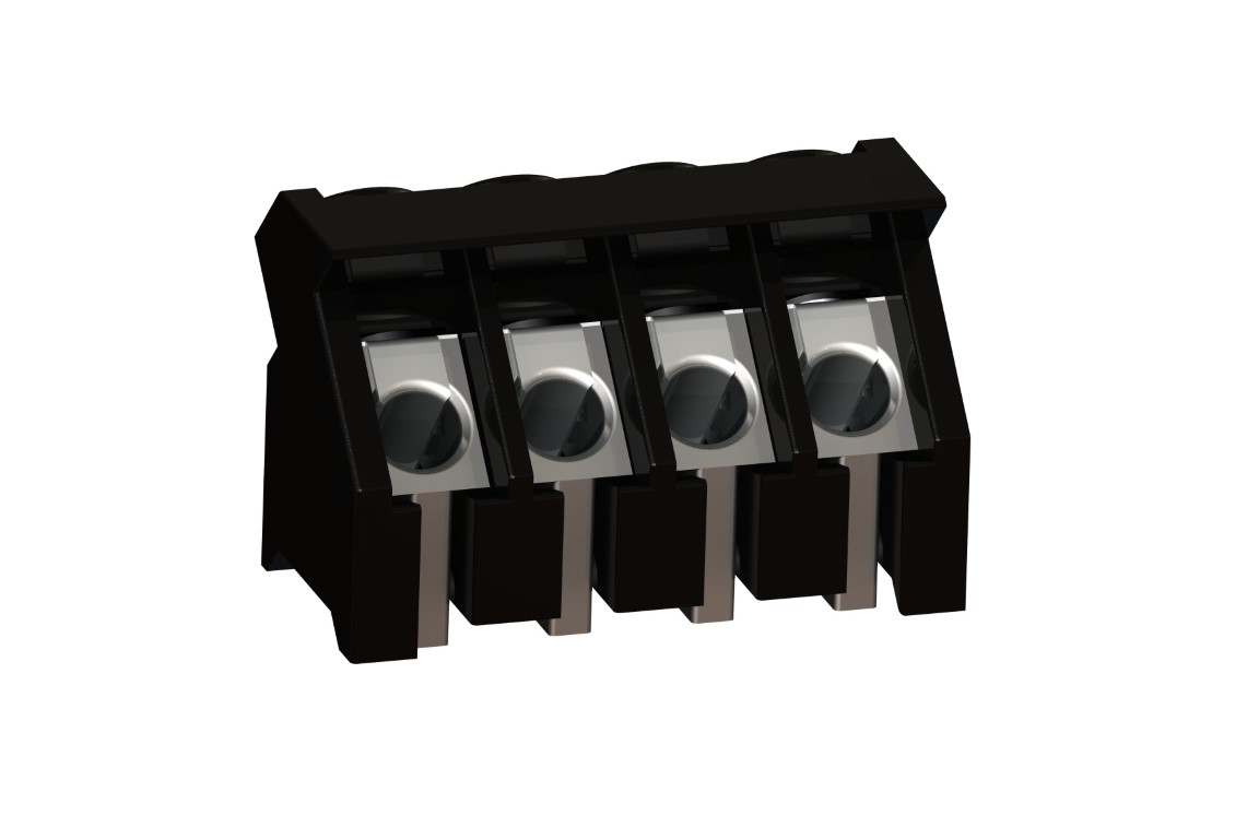
PCB Connector for SMD
Screw connection, 45° wire entry
DESCRIPTION
By creating the 974-D-SMD-DS, WECO offers a PCB terminal for the reflow soldering process with a pitch of 5 mm in true surface mount technology. The wire entry has a connection angle of 45° to the PCB. This offers the advantage that terminal rows can be located space savingly one behind the other. The housing material consists of high temperature resistant plastic and is specially designed in order to assure a good hot-air circulation during the reflow soldering process in the convection oven. The wire entry side of the terminal has to be placed in flowing direction. The screws are turned in to the optimal length of engagement by the factory. It is not to be excluded that the position of the screws may change by transport. Therefore it can be necessary that the screw has to be turned back for using the maximum permissible wire cross-section.
GENERAL INFORMATION
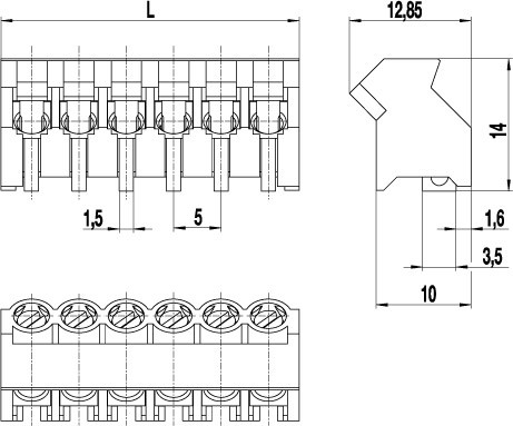
Pitch: 5.00 mm
No. of poles: 2 - 6
TECHNICAL DATA
Clamping Range:
0.75 - 4 mm² / 0.75 - 2.5 mm² / 18 - 12 AWG
Rated cross section: 2.5 mm²
Wire stripping length: 6 mm ± 0.5 mm
Over Voltage Category
III
III
II
Pollution Severity Level
3
2
2
Rated Voltage
250 V
320 V
630 V
Rated Impulse Voltage
4 kV
4 kV
4 kV
Rated current: 24 A
Rated insulation voltage: 250 V acc. to EN 60998-1
Torque: 0.4 Nm
RATINGS
|
Current [A] |
Voltage [V] |
Group |
AWG |
Torque [Nm] |
|
|---|---|---|---|---|---|

|
20 | 300 | B | 18 - 12 | 0.4 |
| 10 | 300 | D | 18 - 12 | 0.4 | |

|
20 | 300 | B | 18 - 12 | 0.4 |
| 10 | 300 | D | 18 - 12 | 0.4 |
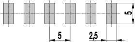
TECHNICAL DRAWINGS
MATERIALS
Moulding: PA HT, black, V-0
Comparative tracking index: CTI ≥ 600
Insulating group: I
Temperature range: -40°C up to 120°C; reflow solder temperature peak max. 255°C acc. to DIN EN 61760-1
Terminal body: Tin plated brass
Screw: M3; zink plated steel, clear passivated
Wire protector: Tin plated tin bronze
OPTIONS / ACCESSORIES
- Consecutive numbering
- Special marking according to drawing
- Self-adhesive marking strip BST-5,00 [1]


