

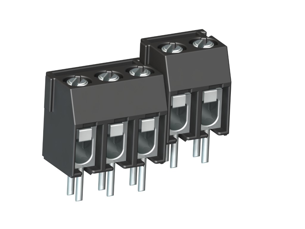
978-TY (-DS)
PCB Connector
Screw connection, 2 solder pins per pole, dovetail version, enlarged clamping area
DESCRIPTION
The PCB connector 978-TY with larger conductor space and a pitch of 5 mm is available in 2- and 3-pole design. Equipped with two solder pins per pole, these PCB connectors offer a tighter fit on the PCB, particularly at smaller pole numbers, and also feature higher non-twist reliability when connecting the terminal lead. Lateral latching elements on the housing allow to latch the PCB connector to longer terminal strips without pole loss. The wire protector of the “DS”-version reliably prevents damage to multi-wire flexible conductors by the turning screw. The wire entrance is parallel to the PCB. The screws are secured against self-loosening. For the grid connection, these PCB connectors are equipped with a M3 thread.
GENERAL INFORMATION
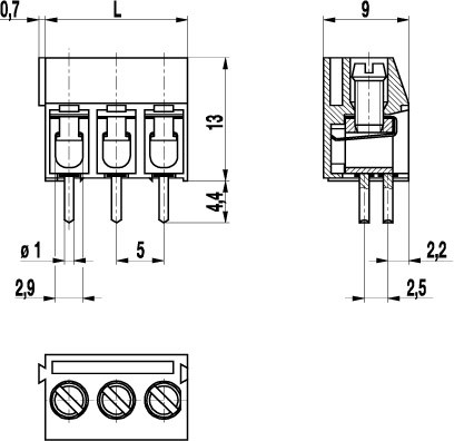
Pitch: 5.00 mm
No. of poles: 2 + 3
TECHNICAL DATA
Clamping Range:
without wire protector
with wire protector:
Rated cross section: 2.5 mm²
Wire stripping length: 6.5 mm ± 0.5 mm
Over Voltage Category
III
III
II
Pollution Severity Level
3
2
2
Rated Voltage
250 V
320 V
630 V
Rated Impulse Voltage
4 kV
4 kV
4 kV
Rated current: 24 A
Hole in PCB: ø 1.3 mm
Torque: 0.5 Nm
RATINGS
|
Current [A] |
Voltage [V] |
Group |
AWG |
Torque [Nm] |
|
|---|---|---|---|---|---|

|
20 | 300 | B | 22-12 [1] | 0.51 |
| 10 | 300 | D | 22-12 [1] | 0.51 | |

|
20 | 300 | B | 26 - 12 | 0.51 |
| 10 | 300 | D, E | 26 - 12 | 0.51 |
| Current [A] |
Voltage [V] |
Cross Section [mm2] |
AWG |
TORQUE |
|
|---|---|---|---|---|---|

|
24 | 400 | 4.0 |
TECHNICAL DRAWINGS
MATERIALS
Moulding: PA, grey, V-0
Comparative tracking index: CTI ≥ 600
Insulating group: I
Temperature range: -40°C up to 100°C
Terminal body: Tin plated brass
Screw: M3; zinc plated steel, blue passivated
Solder pin: ø 1 mm; tin plated copper
Wire protector: Tin plated tin bronze
OPTIONS / ACCESSORIES
- Consecutive numbering
- Special marking according to drawing
- Self-adhesive marking strip BST-5,00
- Longer solder pins up to 95 mm
- Version with extended wire entrance
- Double wire protector as bridge


