

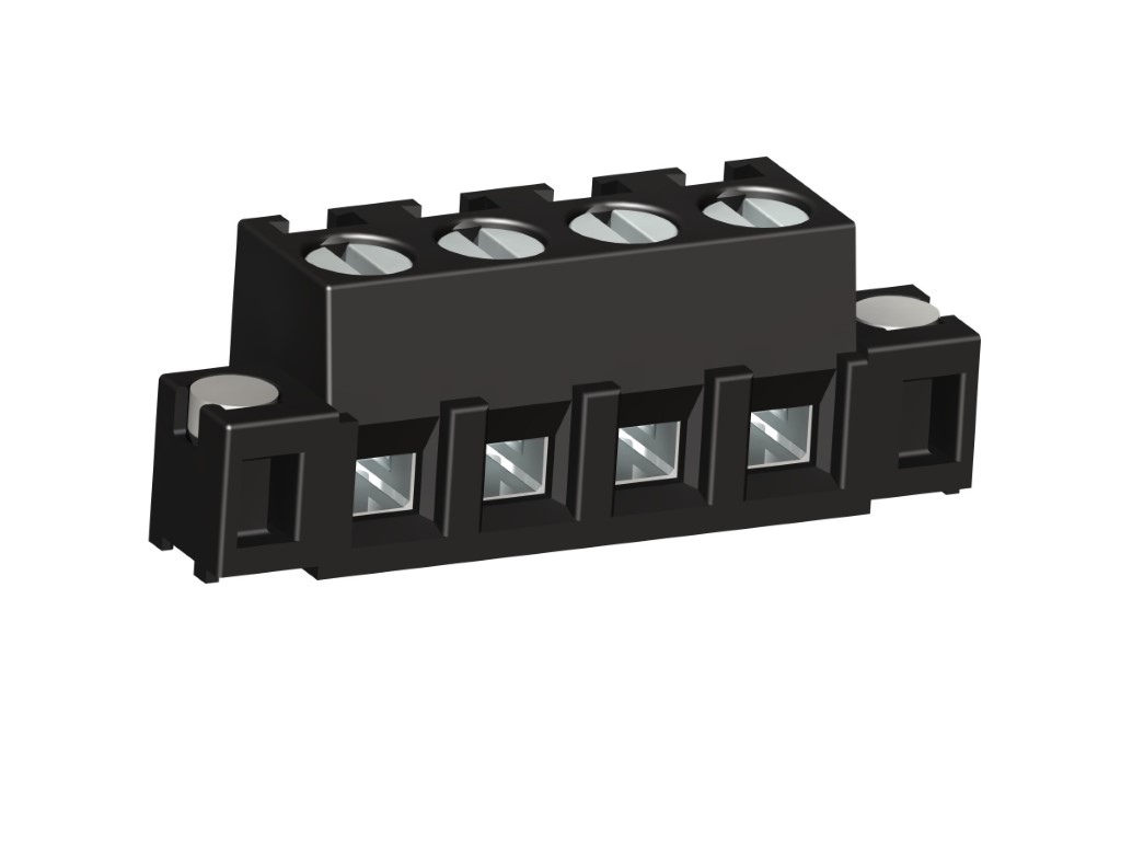
140-A-126-SMD
PCB connector for SMD
Screw connection, with solder flanges
GENERAL INFORMATION
Pitch: 5.00 mm
No. of poles: 2 - 8
Application: Systems for measurement and control
TECHNICAL DATA
Clamping Range:
0.14 - 2.5 mm² / 0.14 - 1.5 mm² / 26 - 16 AWG
Rated cross section: 1.5 mm²
Wire stripping length: 6 mm ± 0.5 mm
Over Voltage Category
III
III
II
Pollution Severity Level
3
2
2
Rated Voltage
200 V
320 V
500 V
Rated Impulse Voltage
4 kV
4 kV
4 kV
Rated current: 16 A
Soldering Process: Reflow solder
Rated insulation voltage: 250 V acc. to EN 60998-1
Torque: 0.5 Nm
RATINGS
|
Current [A] |
Voltage [V] |
Group |
AWG |
Torque [Nm] |
|
|---|---|---|---|---|---|

|
10 [1] | 300 | B, D | 30 - 14 | 0.51 |

|
15 | 300 | B | 30 - 14 | 0.51 |
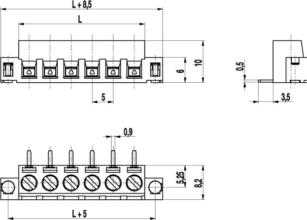
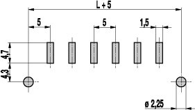
TECHNICAL DRAWINGS
MATERIALS
Moulding: PA HT, black, V-0
Comparative tracking index: CTI ≥ 600
Insulating group: I
Temperature range: -40°C up to 120°C; reflow solder temperature peak max. 255°C acc. to DIN EN 61760-1
Terminal body: Nickel plated brass
Pressure clamp: Tin plated tin bronze
Screw: M3; zinc plated steel, blue passivated
Solder pin: 0,9 x 0,5 mm; tin plated tin bronze
Solder Cylinder: Tin plated brass
OPTIONS / ACCESSORIES
- Consecutive numbering
- Special marking according to drawing
- Self-adhesive marking strip BST-5,00 [2]


