

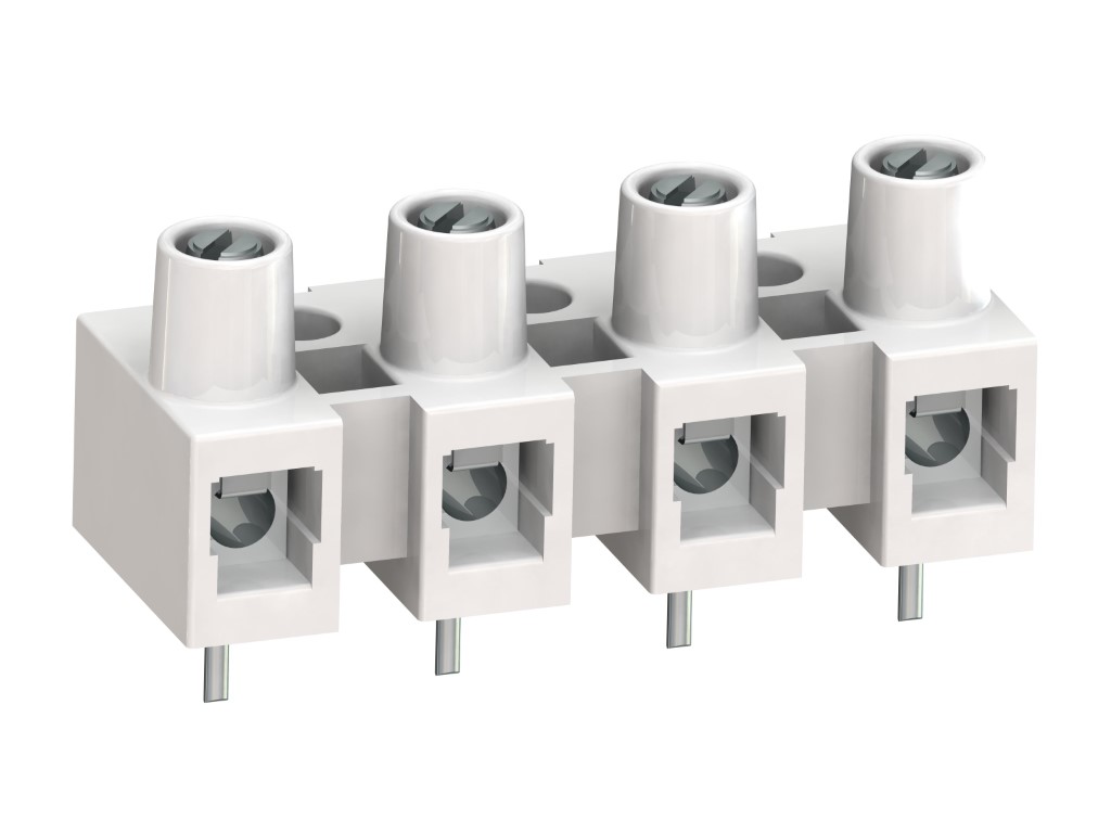
322-G (-DS)
PCB Terminal Strip
Screw connection, with solder pin
DESCRIPTION
The socket terminal strip 322-G is available in 10 mm pitch with 1- to 12-pole design and can be easily stripped to the desired number of poles. The flexible polyamide moulding can even be mounted on curved surfaces. Due to large pitch and moulding shape, this version is also well suited for applications using higher voltages. The 322-G version features reliable contact protection and long clearance and creepage distances. The captive screws are vibration-proof and secured against self-loosening. In addition to be soldered in with solder pins, the terminal strips can be screw-mounted onto the PCB. The wire protector of the “DS”-version reliably prevents damage to multi-wire flexible conductors by the turning screw. The terminal lead insertion depth is not limited.
GENERAL INFORMATION
Pitch: 10.00 mm
No. of poles: 2 - 12
TECHNICAL DATA
Clamping Range:
without wire protector
with wire protector:
Rated cross section: 2.5 mm²
Wire stripping length: 8 mm ± 0.5 mm
Over Voltage Category
III
III
II
Pollution Severity Level
3
2
2
Rated Voltage
1000 V
1000 V
1000 V
Rated Impulse Voltage
8 kV
8 kV
6 kV
Rated current: 15 A
Rated insulation voltage: 750 V acc. to EN 60998-1
Torque: 0.5 Nm
RATINGS
|
Current [A] |
Voltage [V] |
Group |
AWG |
Torque [Nm] |
|
|---|---|---|---|---|---|

|
20 | 300 | B | 18 - 12 | 0.51 |

|
300 | 20 | B | 26-10 [1] | 0.51 |
| 10 | D,E | 26-10 [1] | 0.51 |
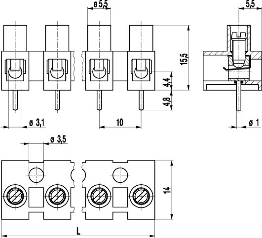
TECHNICAL DRAWINGS
MATERIALS
Moulding: PA, natural, V-2
Comparative tracking index: CTI ≥ 600
Insulating group: I
Temperature range: -40°C up to 100°C
Terminal body: Nickel plated brass
Screw: M3; zinc plated steel, blue passivated
Tab: Nickel plated brass
Wire protector: Tin plated tin bronze
OPTIONS / ACCESSORIES
- Marking strips BST-322
- Jumper 322-J
- Longer solder pins up to 75 mm
- G30: Gold Plating (30 micro inches)


